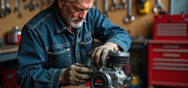
The valve adjustment on a Briggs and Stratton engine determines the stability of the speed, the available power, and the longevity of the block. A poorly calibrated clearance, even by a few hundredths of a millimeter, is enough to cause compression losses, erratic idling, or premature wear of the valve seats.
Briggs and Stratton Valve Clearance: Why Tolerances Vary by Model
The Briggs and Stratton service manuals distinguish several clearance ranges depending on the type of cylinder head and the engine series. Some OHV models specify a clearance of about 0.10 mm at the intake and 0.15 to 0.20 mm at the exhaust, whereas older series tolerated wider values, around 0.15 to 0.20 mm at the intake.
This difference is not trivial. An intake clearance that is too wide reduces cylinder filling, increases mechanical knocking, and amplifies speed variations under load. An exhaust clearance that is too tight prevents the valve from closing completely when hot, creates abnormal residual compression, and disrupts the operation of the mechanical governor.
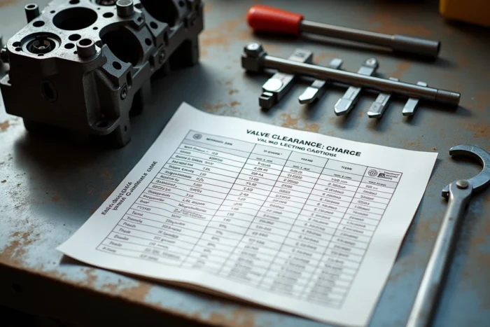
Before any intervention, the first step is to identify the exact series of the engine (engraved on the casing or on the nameplate) and to consult the corresponding service manual. A Briggs and Stratton valve adjustment table summarizes the values by model and avoids approximations.
Mechanical Governor and Valves: An Often Ignored Interaction
The mechanical governor continuously adjusts the throttle opening to maintain a stable speed. Its return spring works with very precise tension, on the order of a few millimeters of travel. This system cannot compensate for a valve problem.
When the exhaust clearance is insufficient, the valve remains partially open for a fraction of the cycle. The cylinder does not build pressure correctly, the crankshaft experiences jolts, and the governor constantly tries to correct this. The result: a speed that oscillates cyclically, sometimes mistakenly confused with a carburetor or governor spring issue.
Conversely, excessive intake clearance degrades filling and causes a drop in torque at low speed. The engine seems to lack power under load, for example when mowing on sloped terrain. User feedback varies on this point: some users fix the problem by retightening the governor spring, which only masks the defect without resolving it.
The correct sequence is to adjust the valves first, then check the tension of the governor spring. Reversing this order is like calibrating a measuring instrument on a distorted basis.
OHV Engine Valve Adjustment: Step-by-Step Method
The adjustment is done with the engine cold, piston at top dead center (TDC) on the compression stroke. This position ensures that both valves are closed and that the rockers are not under load.
- Remove the rocker cover after disconnecting the spark plug (to prevent accidental starting). Clean the area around the gasket to avoid introducing debris into the cylinder head.
- Manually turn the crankshaft (via the key on the flywheel nut or by turning the blade on a mower) until you feel the maximum compression resistance. Check that both rockers have free play at this stage.
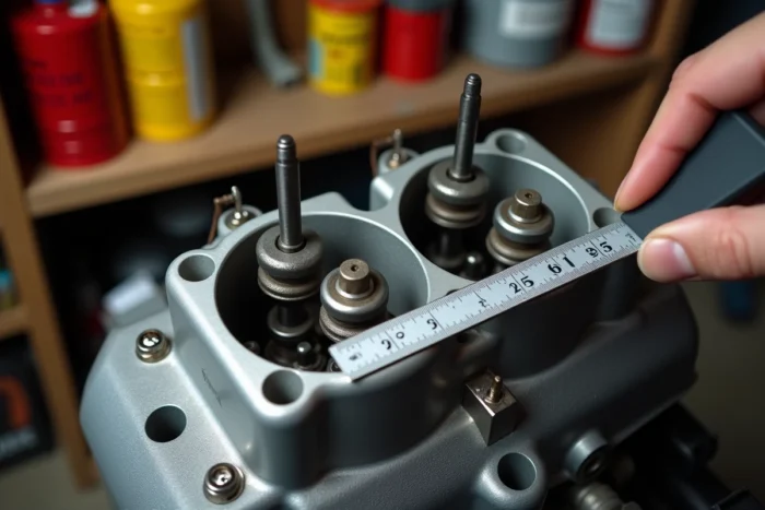
- Insert a feeler gauge between the rocker and the valve stem. The gauge should slide with slight resistance, without forcing or floating freely.
- Adjust the rocker adjustment nut while holding the pivot screw, then tighten the lock nut without changing the position. Recheck the clearance after tightening, as the locking torque can shift the value.
- Repeat the operation on the second valve, using the specific value (intake or exhaust) for the model.
Always recheck the clearance after tightening the lock nut. This is the most common mistake: the tightening torque slightly turns the adjustment screw, and the final clearance differs from that measured before locking.
Identifying the Intake and Exhaust Valves
On a Briggs and Stratton OHV single-cylinder engine, the intake valve is located on the carburetor side (intake manifold), and the exhaust valve is on the muffler side. In case of doubt, the exhaust valve often has a slightly smaller head diameter and more pronounced thermal coloration marks.
Valve Adjustment Errors and Consequences for the Engine
A mispositioned piston skews the entire operation. If the crankshaft is set on the exhaust stroke instead of the compression stroke, one of the valves is in the process of lifting, and the measurement of the clearance makes no sense. The piston must be at TDC compression, not TDC exhaust.
Using a worn or deformed feeler gauge is another classic trap. Cheap gauges lose their precision after a few dozen uses. With tolerances as fine as 0.10 mm, a gauge widened by 0.02 mm already represents a significant error.
Dirty or pitted valves pose a different problem. Pitting on the seat or valve face creates compression leaks that adjusting the clearance will not fix. Briggs and Stratton recommends visually inspecting the valves during each adjustment and performing a lapping or replacement if cracks, grooves, or pits appear on the face.
| Observed Symptom | Probable Valve-Related Cause |
|---|---|
| Unstable speed, cyclical oscillations | Exhaust clearance too low, governor disturbance |
| Power loss under load | Intake clearance too wide, insufficient filling |
| Mechanical knocking at idle | Excessive play on one or two rockers |
| Hard starting when cold | Exhaust valve not closing completely |
| Abnormal consumption | Pitted or cracked valve, compression leak |
Valve adjustment remains an accessible operation with limited tools (feeler gauge set, wrench, screwdriver), but its precision directly affects the engine’s reliability throughout a season. An annual check or every 300 hours of operation allows for detecting a drift before it causes damage to the seats or valve guides.